stc1000p
STC-1000+ One vessel brew system controller
This is a firmware and Arduino based uploader for the STC-1000 dual stage thermostat. The purpose is to serve as a simple semi-automatic controller for a one vessel brewing system.

Features
- Both Fahrenheit and Celsius versions
- Cheap, simple, semi automated one vessel brewing control
- Controls a pump and one or two heaters
- Alarm when user interaction is required
- Possible to delay heating of strike water
- User definable power output at different stages in the program
- Manual control
- 1-6 mash steps, 0-4 hop addition alarms
- Pause program at any time
- Button acceleration, for frustrationless programming by buttons
Parameters
| Menu item | Description | Values |
|---|---|---|
| Sd | Strike delay | 0-999 minutes |
| St | Strike water setpoint | -40.0 to 140°C or -40.0 to 250°F |
| SO | Strike output (also used to reach hotbreak and between mash steps) | 0-200% |
| Pt1 | Mash step 1 setpoint | -40.0 to 140°C or -40.0 to 250°F |
| Pd1 | Mash step 1 duration | 0-999 minutes |
| Pt2 | Mash step 2 setpoint | -40.0 to 140°C or -40.0 to 250°F |
| Pd2 | Mash step 2 duration | 0-999 minutes |
| Pt3 | Mash step 3 setpoint | -40.0 to 140°C or -40.0 to 250°F |
| Pd3 | Mash step 3 duration | 0-999 minutes |
| Pt4 | Mash step 4 setpoint | -40.0 to 140°C or -40.0 to 250°F |
| Pd4 | Mash step 4 duration | 0-999 minutes |
| Pt5 | Mash step 4 setpoint | -40.0 to 140°C or -40.0 to 250°F |
| Pd5 | Mash step 4 duration | 0-999 minutes |
| Pt6 | Mash step 4 setpoint | -40.0 to 140°C or -40.0 to 250°F |
| Pd6 | Mash step 4 duration | 0-999 minutes |
| PO | Mashing output | -200 to 200% |
| Ht | Hot break temperature | -40.0 to 140°C or -40.0 to 250°F |
| HO | Hot break output | -200 to 200% |
| Hd | Hot break duration | 0-999 minutes |
| bO | Boil output | -200 to 200% |
| bd | Boil duration | 0-999 minutes |
| hd1 | Hop alarm 1 | 0-999 minutes |
| hd2 | Hop alarm 2 | 0-999 minutes |
| hd3 | Hop alarm 3 | 0-999 minutes |
| hd4 | Hop alarm 4 | 0-999 minutes |
| tc | Temperature correction | -5.0 to 5°C or -10.0 to 10.0°F |
| APF | Alarm/Pause control flags | 0 to 511 |
| PF | Pump control flags | 0 to 31 |
| Pd | Set heating period interval | 1.0 to 20.0 seconds |
| cO | Manual mode output | -200 to 200% |
| cP | Manual mode pump | 0 (=off) or 1 (=on) |
| cSP | Manual mode thermostat setpoint | -40.0 to 140°C or -40.0 to 250°F |
| ASd | Safety shutdown timer | 0-999 minutes |
| rUn | Run mode | OFF, Pr (run program), Ct (manual mode thermostat), Co (manual mode constant output) |
Note on APF parameter: APF is a parameter that holds flags to enable/disable the alarm/pause points during the program. By default all alarms/pause points are enabled, but this parameter allows the user to skip some/all of them if so desired. To make adjustments, the desired behaviour needs to be calculated.
| Value | Description |
|---|---|
| 1 | Strike temp reached/dough in alarm |
| 2 | Strike temp reached/dough in pause |
| 4 | Mash done/sparge/start boil up alarm |
| 8 | Mash done/sparge/start boil up pause |
| 16 | Hop addition 1 alarm |
| 32 | Hop addition 2 alarm |
| 64 | Hop addition 3 alarm |
| 128 | Hop addition 4 alarm |
| 256 | Boil done/start chill alarm |
Add up the values for the alarms/pause points desired, and set that value to the APF parameter. Say for example you’d like to mash in cold, and want the controller to skip the alarm and pause after strike temp is reached, and just continue with the mash profile (but still keep the other alarms/pause points). Then sum up all the alarms (511) and subtract 1 (strike temp reached alarm) and 2 (strike temp reached pause). The value (508) is what you’d want to enter in APF.
Note on PF parameter: The PF parameter holds flags to indicate pump status during different stages of the program. By default the pump is on during the mash.
| Value | Description |
|---|---|
| 1 | Pump during heating of strike water |
| 2 | Pump during ramping up to reach next mash steps |
| 4 | Pump during the mash steps |
| 8 | Pump during heating up to reach hot break |
| 16 | Pump during hot break |
Similar to the APF parameter. Add upp the values of the stages when the pump should be active and enter it into the PF parameter.
Hardware usage
Pretty simple really. The two output relays can be used to control heaters. Either directly och replaced by solid state relays. The output is specified in percent and is controlled with slow PWM (that is they are pulsed on/off). 0-100% controls heater 1 (heat relay), 100-200% controls heater 2 (cool relay). So for example, if an output of 75% is specified, heater 1 will be on 75% of the time and heater 2 will be off. At 125% heater 1 will be on and heater 2 will be on 25% of the time. A negative percentage value is also allowed, which does the exact same thing, but with the elements reversed. This could be useful if during mashing for example, a lower power element is preferred over a higher powered one.
The output percentage is also used in thermostat mode, so if temperature is below setpoint, the output will be the specified one. If output is at or over the setpoint the output will be 0.
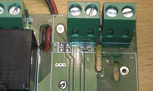
The unpopulated terminal on the STC can be used as pump control. The firmware will put this output in high impedance to turn pump on and pull it low to turn pump off.

Fig 1: Connection terminal of the LED dimmer
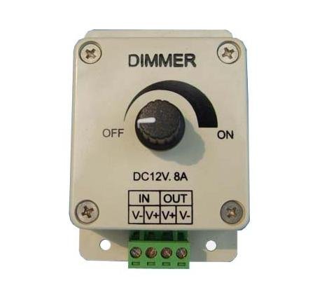
This can be used directly with an 8A LED dimmer for flow control of a 12V pump.

Fig 2: LED dimmer
The schematic of the dimmer shows, that if you connect this output to the center pin of the potentiometer, you can switch between off and the manual setting.
Note that you need to have a common ground for the STC and the dimmer.
Fig 3: LED dimmer schematic
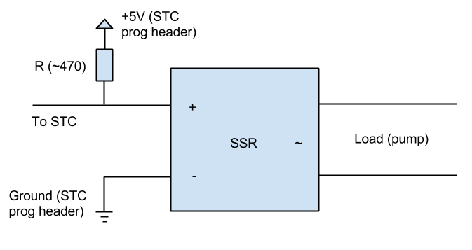
Or, you could also use the output to control a mains powered pump using a solid state relay.

Fig 3: SSR pump control connection
Connect the positive input of the SSR to the pin on the STC and add a pullup resistor (220-470 ohm) to +5v (you can find that on the programming header on the STC). Connect the negative input on the SSR to ground (can also be found on the STC programming header).
Program algorithm
- Wait Sd minutes (with all outputs off)
- Wait until temp >= St (or end program if countdown = 0)
- Thermostat on with output PO
- St alarm if APF flag set, countdown = ASd minutes
- Wait until keypress (or end program if countdown = 0)
- Pause if APF flag set (output off, pump off)
- (This is when you dough in and do manual vorlauf)
- Wait until power key is pressed
- x = 1
- Init mashstep: Thermostat off, set output to SO, pump on if PF flag set, countdown = ASd minutes
- Wait until temp >= Ptx (or end program if countdown = 0)
- Thermostat on with output PO, countdown = Pdx, pump on if PF flag set
- Wait until countdown = 0
- x = x+1
- if x<=6 goto Init mashstep
- bU alarm if APF flag set, countdown = ASd minutes
- Wait until keypress (or end program if countdown = 0)
- Pause if APF flag set (output off, pump off)
- (This is when you remove grains and sparge)
- Wait until power key is pressed
- Thermostat off, output = SO, pump on if PF flag set, countdown = ASd minutes
- Wait until temp >= Ht (or end program if countdown = 0)
- Output = HO, countdown = Hd minutes, pump on if PF flag set
- Wait until countdown = 0
- Output = bO, countdown = bd minutes, pump off
- Wait until countdown = 0, if countdown = hdx then hdx alarm if APF flag set
- Ch alarm if APF flag set, output = 0, pump off, end program
During the program, a single press on the power button will pause the program (during pause, a LED will flash and all outputs will be off). Press the power button again and the program will resume.

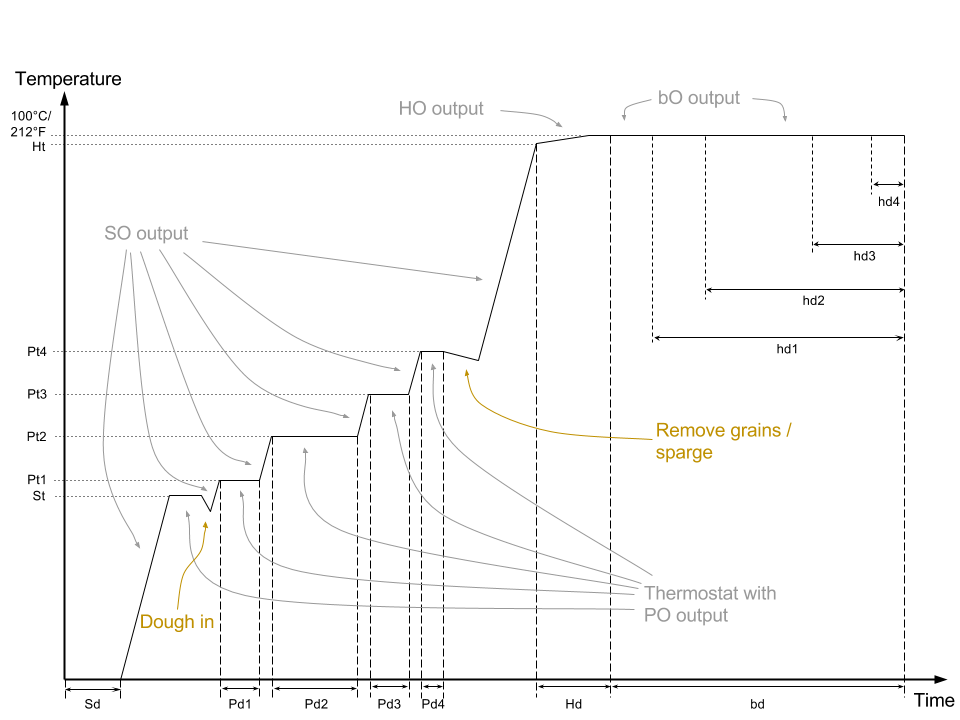
Fig4: Graphical representation of the algorithm
Now, I will try as best I can, to explain the algorithm and key concepts in ‘english’.
The program starts off with a delay of Sd minutes (strike delay), during this time it will do nothing but wait. This can be useful if you want to delay the heating of strike water, so it will be warm by the time you need it (don’t recommend leaving it unattended, do so at your own risk). Sd can of course be set to 0 to start immediately.
Reaching strike temperature is done using SO output, and as you probably want to do this as fast as possible, you’d want to set SO to 100% (if you use one heating element) or 200% (for two elements), though you can use what will suit you and your system best.
Once strike temperature is reached, the alarm will go off if the corresponding APF flag is set and ‘St’ will flash on the display. It will also switch to thermostat mode with PO output. That means if/when temperature is below St, output will be PO. If it is at, or above St, output will be 0.
If the alarm is not acknowleged within ASd (automatic shutdown delay) minutes, the program will be stopped. Once acknowledged (by pressing any button), the program will pauseif the corresponding APF flag is set (all outputs off) and during this pause you dough in your grains. Press the power button to continue the program.
In a similar way, for each of the mashing steps, SO will be used to reach the temperature fast, then switch to thermostat mode with PO output and hold the mash step temperature for the programmed duration.
When mashing is done, the alarm will go off again (again if the corresponding APF flag is set) and ‘bU’ (boil up) is flashing on the display. Thermostat action is still used. Acknowledge the alarm and the unit will pause (APF flag…) again. Remove the grains and optionally sparge manually. Press power button to resume.
SO output will be used to raise temperature quickly. Once Ht (hotbreak temperature) is reached, output is switched to HO (hotbreak output) for Hd (hotbreak duration) minutes. The purpose of this, is that as the wort reaches boiling temp, proteins clump together and a foam is formed on the surface. The added nucleation points as well as the insulating effect of the foam can easily contribute to boil over. The heat will shortly break down the proteins (hot break), that will settle to the bottom of the kettle. So, to avoid boil over the power is reduced during this period. As an educated guess, you might want to set Ht a degree or so shy of your normal boiling temperature. HO will probably be around 75% of bO and Ht should probably be around 15 minutes.
When Hd has passed, normal boil starts, with bO output. The timer also starts counting down the boil duration bd. When the timer matches a hop addition the alarm will sound and hdx will flash on the display. Acknowledge the alarm by pressing any button (and add the hops of course). Note that the hdx settings are in standard hop addition times as used in most recipies, that is the boil duration counted back from boil end.
Once the boil is completed, output is turned off and the alarm goes of (flashing ‘Ch’ for chill). Acknowledge and chill your wort.<p>
An important note on ASd. This is in my opinion an important feature. Many of the steps in the program are timed. For example mash durations, boil duration and so on. But not every step is, for example, when ‘stepping up’ the temperature, the program will continue to heat until the temperature is reached, or during an alarm (except hop additions, during which the boil duration timer is running) when user input is required, during these times the timer is loaded with ASd instead and if not the condition is met within this timeframe, the program stops. This is of course for safety. ASd should therefore be set to the maximum of these duration + some wiggle room. For example, if it takes you around 35 minutes to reach strike temp and this is the longest of these delays, maybe set ASd to 45 minutes.
Also, a note on Pd. Power is controlled by pulsing on/off to the heating element. The lenght of an on/off cycle can be set with Pd. If you are using elements with high power draw (high in this context would probably be in the order of more than 1.5kW), exchanging the relays in the STC for an external solid state relay is probably a good idea. Using a solid state relay, a shorter period time is not a problem. Using the mechanical relays, you would probably want a longer period time, to limit wear from excessive switching. Though this can cause ‘pulsating’ boil and possibly wort scorching during mashing (depending on your setup of course).
Updates
| Date | Release | Description |
|---|---|---|
| 2015-XX-XX | v1.00 | First release |